
SonicSniffer® applications
The SonicSniffer® main application is to perform routine inspection of power ultrasonic equipment for the early detection of frequency shifts, which indicates the need for preventive maintenance. Frequency shifts alert users that something is not right, possibly avoiding equipment failure and saving expenses with new converters, boosters, horns, sonotrodes, blades and tips.
Frequency shifts are due to many causes, such as joint deterioration, horn wear, cracks and converter failure. Joint deterioration is the most common issue because it is an inevitable. Over the time, it decreases the stack frequency, mechanical quality factor and overall efficiency because of the reduced effective contact area and increased friction of interfaces. Low efficiency leads to heating, which accelerates the mating surfaces fretting and the ultrasonic components fatigue in a vicious circle , ultimately leading to a catastrophic failure. By taking care of the stack joints, users may avoid triggering many other problems.
SonicSniffer® is also used to test the frequency of ultrasonic medical equipment and components, such as ultrasonic scalers tips and ultrasonic scalpels blades.
Stack verification and preventive maintenance
Step 1 - Frequency test
Step 1 involves reading the stack frequency whilst the equipment is running. In order to do that, bring SonicSniffer® close to the ultrasonic horn, sonotrode or ultrasonic tip operating load free to read the frequency. If the power generator is analog, make sure it is finely tuned before perfoming the frequency reading.

For high grade ultrasonic welding machines, deviations higher than 0.25 % with respect to operation baseline indicate the need for preventive maintenance. For equipment in general, the assessment can be based on prior knowledge of the operating frequency.
Typical frequency range of ultrasonic welding machines.| Nominal | Minimum | Maximum |
| 20 kHz | 19.950 kHz | 20.050 kHz |
| 40 kHz | 39.900 kHz | 40.100 kHz |
We recommend daily readings of frequency (prevention is best way to avoid further problems and unnecessary expenses).
Step 2 - Surfaces visual inspection
Once a frequency shift greater than 0.25% (or greater than the tolerance specified by the manufacturer) is detected, disassemble the acoustic stack joints and remove the threaded studs using proper tools, carefully avoiding scratches. Prior the visual inspection, wipe the mating surfaces with paper towels moistened with cleaning solvent and clean the studs by brushing or ultrasonic cleaning them.

Inspect the mating surfaces for fretting, circular wear areas, hard deposits, corrosion and rust. In case of any problem, proceed to reconditioning (Step 3). Inspect the threaded studs for wear, cracks, damages and galling. If replacement is needed, observe the manufacturer specifications (do not replace titanium studs by steel ones or vice versa). It is usual to find cracked studs when the tightening torque is not proper controlled.

Damaged mating surfaces and studs decrease the stack frequency, mechanical quality factor and overall efficiency because of reduced effective contact area and increased friction between the interfaces. Low efficiency leads to heating, which accelerates surfaces fretting and the ultrasonic components fatigue in a vicious circle, ultimately leading to a catastrophic failure.
Step 3 – Surfaces reconditioning The surfaces reconditioning consists in restoring their finishings and flatness. To perform this work, you need silicon carbide sandpapers grit #280, #400 and #600 and a granite surface plate (12"x 18" x 3" is enough and cheaper than a new ultrasonic component). A mirror is an acceptable alternative in the absence of a granite surface plate. If the component mating surface is badly damaged, start with sandpaper #280; otherwise, start with #400.


Tape a clean sheet on the granite surface plate and carefully stroke the component in one direction, taking great care to prevent piece tilting during this operation. Perform the strokes interspersing 120° rotations. Apply limited pressure, only enough to avoid tilting. Before moving to the next sandpaper, repeat this process until the surface is recovered. When swapping sandpapers, clean surfaces and parts to prevent contamination with coarse grains from the previous sandpaper. Important note: sanding will shorten the part and increase the frequency by a few Hertz, so remove as little material as possible.

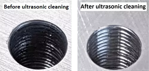
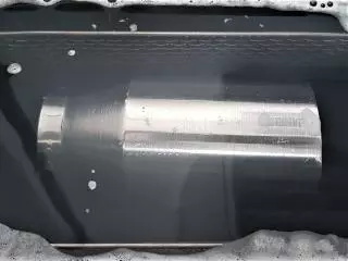
After recovering the surfaces, clean them with an ultrasonic cleaner or with paper towels moistened with cleaning solvent (ultrasonic cleaning is the best option). Ultrasonic cleaning is effective because it will also fine clean the stud holes and remove any grit residue. If using ultrasonic cleaning on the converters, ensure to keep the ceramics region dry, as well as the O-rings region on the boosters. After the stack components are clean and dry, inspect them for flatness and parallelism. It should be equal to or better than 0.025 mm (.001”).
It may not be possible to recondition some ultrasonic components surfaces, such as the front of cone-shaped 15 kHz boosters and high frequency converters because during sanding they usually tilt and that results in crowning. If that is the case, do nothing, because a crowned surface is worse than a poor one.
Step 4 – Stack reassembly
Firstly, protect the mating surfaces to reduce the joints degradation rate. In the absence of any manufacturer specifications, coat the mating surfaces with a very thin film of high temperature molybdenum-based grease or high-pressure silicone-based grease. This thin film maximizes the coupling by compensating the surface roughness and avoiding the components cold welding. Important note: never apply any grease or lubricant on the studs’ threads, they should be absolutely clean and dry as well the stack components’ threads.

Secondly, reinsert the studs as per the manufacturer instructions (replace if damaged). In the case of missing specifications, do not apply tightening over 2 Nm (≈ 0.2 kgfm).

Thirdly, put the acoustic stack parts together (converter + booster, then converter-booster + horn) using proper tools to avoid scratches and apply torque wrench as per the manufacturer’s instructions. In the case of missing specifications, consider the suggestions on the table below.
Important note: Do not hold the booster by its mounting rings or the converter by its housing can.
| Stack frequency | Torque |
| 15 kHz | 40 Nm (≈ 4 kgfm) |
| 20 kHz | 35 Nm (≈ 3.5 kgfm) |
| 30 kHz | 25 Nm (≈ 2.5 kgfm) |
| 40 kHz | 20 Nm (≈ 2.0 kgfm) |
Finally, reinstall the ultrasonic stack in the welding machine and test it for frequency with the SonicSniffer. The frequency shift must be reduced; otherwise there may be a failed component. If the frequency shift persists, test the stack to identify which element is not working properly..
Learn more about the SonicSniffer®